i pocket

JKM PMM i-pocket
Powered by Conduit Mobile

ad by nuffnang

Tuesday, September 16, 2008

AC Theory


AC THEORY: AC Ohm's Law.
Ohm's Law can also be applied to AC circuits. However, alternating currents and voltages are continually changing. At the beginning of the cycle the voltage and current are zero, building to peak positive values at 90°, before declining back to zero, and then repeated in a negative direction.

It is therefore only possible to calculate instantaneous values of V or I throughout the cycle. Peak or RMS values are normally used.

The AC resistance of capacitors and inductors is called 'reactance' (measured in Ohms). As the frequency is increased, capacitive reactance decreases, whereas inductive reactance increases.
Once the reactance is calculated for C or L at the applied frequency, the value can be inserted in the formula as for resistance. Where there is a combination of resistance and reactance the calculation refers to 'impedance', symbol Z.
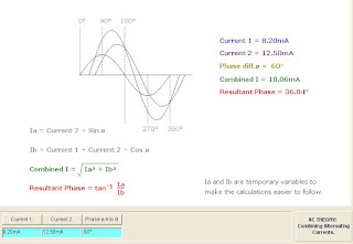
AC THEORY: Combining Alternating Currents.

When two or more currents flow in a DC circuit they can be added or subtracted directly. For parallel AC circuits the currents will be at phase angles determined by the circuit capacitive and inductive elements.
One way the resultant can be found is graphically as shown, by measuring the amplitudes of the instantaneous values for A and B throughout the waveform and adding. The resultant phase angle will tend to be towards the current making the greatest contribution to the resultant.
Phase differences greater than 90° are not considered, but it should be understood that they do arise in practical circuits.
The use of phasors is another approach. Select 'phasor diagrams topic' for an explanation.
AC THEORY: Voltage and Current for R.
For the parallel AC circuit the voltage is common across all current branches of R, C and L. However, the current for each branch will have a phase angle determined by the resistive, capacitive or inductive element of that component.
For the capacitor, the current will 'lead' the voltage and for the inductor current will 'lag' the voltage. Whereas resistor currents and voltages will always be in phase.
The instantaneous amplitudes of both voltage and current can be found at any point throughout the AC waveform for phase angles of 0 to 360°.

AC THEORY: Voltage and Current for C.
For the parallel AC circuit the voltage is common across all current branches of R, C and L. However, the current for each branch will have a phase angle determined by the resistive, capacitive or inductive element of that component.
For the capacitor, the current will 'lead' the voltage and for the inductor current will 'lag' the voltage. Whereas resistor currents and voltages will always be in phase.
The instantaneous amplitudes of both voltage and current can be found at any point throughout the AC waveform for phase angles of 0 to 360°.


AC THEORY: Voltage and Current for L.
For the parallel AC circuit the voltage is common across all current branches of R, C and L. However, the current for each branch will have a phase angle determined by the resistive, capacitive or inductive element of that component.
For the capacitor, the current will 'lead' the voltage and for the inductor current will 'lag' the voltage. Whereas resistor currents and voltages will always be in phase.
The instantaneous amplitudes of both voltage and current can be found at any point throughout the AC waveform for phase angles of 0 to 360°.

Wednesday, August 6, 2008

JENIS - JENIS LITAR ELEKTRIK

Litar elektrik merupakan suatu susunan pengalir atau kabel untuk membawa arus dari punca bekalan voltan ke komponen-komponen elektrik (beban). Ianya terbahagi kepada dua iaitu:

1.3.1 Litar Lengkap
Ia juga dikenali sebagai litar asas atau litar mudah (Rajah 1.1). Ia merupakan suatu penyambungan tertutup yang membolehkan arus mengalir dengan sempurna iaitu arus mengalir dari bekalan dan balik semula ke bekalan tersebut. Litar-litar tersebut mestilah terdiri daripada voltan bekalan (V), arus elektrik (I) dan rintangan (R).

1.3.2 Litar Tidak Lengkap
Litar tidak lengkap ialah litar yang mengalami kekurangan salah satu daripada tiga perkara tersebut iaitu samada voltan bekalan atau rintangan beban. Pengaliran arus tidak akan berlaku dengan sempurna pada litar tidak lengkap. Litar tidak lengkap terbahagi kepada dua ;

1.3.2.1 Litar buka - litar dimana punca beban dalam litar tersebut dibuka. Oleh itu tiada pengaliran arus berlaku. Nilai rintangan dalam litar adalah terlalu tinggi. Rajah 1.2 menunjukkan satu contoh litar buka.

1.3.2.2 Litar pintas - sambungan pada punca bebannya dipintaskan dengan menggunakan satu pengalir yang tiada nilai rintangan. Ia ditunjukkan seperti Rajah 1.3 Arus yang mengalir adalah terlalu besar. Biasanya jika berlaku litar pintas, fius akan terbakar.

Tuesday, June 10, 2008

UNIT 1 - PENGENALAN, KUANTITI ASAS DAN RINTANGAN

1.0 PENGENALAN KEPADA ELEKTRIK

Elektrik adalah merupakan satu tenaga yang tidak dapat dilihat tetapi boleh dirasai dan digunakan oleh manusia pada hari ini dan akan datang. Tenaga elektrik dapat dihasilkan kesan daripada tindakan:-
a) Geseran
b) Haba
c) Aruhan elektromagnet

Tindakan daripada tenaga elektrik boleh ditukarkan kepada beberapa punca tenaga yang
lain yang boleh digunakan seperti:
a) Tenaga cahaya - seperti lampu
b) Tenaga haba - seperti seterika
c) Tenaga bunyi - seperti radio
d) Tenaga gerakan - seperti motor

Elektrik terdiri daripada dua (2) jenis iaitu elektrik statik dan elektrik dinamik.
a) Elektrik Statik – Keadaan di mana tiada pergerakan elektron dalam arah tertentu.
b) Elektrik Dinamik – Keadaan di mana terdapat pergerakan elektron dalam arah
tertentu.


1.1 KUANTITI ASAS ELEKTRIK

1.1.1 Daya Gerak Elektrik (d.g.e)
Daya atau tekanan elektrik yang menyebabkan cas elektrik mengalir. Contoh sumber yang menghasilkan tenaga elektrik adalah bateri dan janakuasa.
Simbol : E
Unit : Volt(V)

1.1.2 Cas Elektrik
Terdiri daripada cas positif dan cas negatif. Kuantiti cas ini dinamakan Coulomb.
Simbol : Q
Unit : Coulomb(C)

1.1.3 Arus
Pergerakan cas elektrik yang disebabkan oleh pergerakan elektron bebas. Ia mengalir dari terminal positif ke terminal negatif.
Simbol : I
Unit : Ampiar (A)


1.1.4 Bezaupaya (voltan)
Perbezaan keupayaan di antara dua titik dalam litar elektrik.
Simbol : V
Unit : Volt(V)

1.1.5 Rintangan
Merupakan penentangan terhadap pengaliran arus.
Simbol : R
Unit : Ohm

1.1.6 Pengalir
Bahan yang membenarkan arus elektrik melaluinya kerana ia mempunyai bilangan elektron bebas yang banyak. Contohnya besi dan kuprum.

1.1.7 Penebat
Bahan yang tidak membenarkan arus elektrik mengalir melaluinya. Ia mempunyai banyak elektron valensi tetapi sukar dibebaskan. Contohnya getah, kaca, minyak dan oksigen.

1.1.8 Separa Pengalir (semikonduktor)
Bahan yang mempunyai ciri-ciri elektrikal di antara penebat dan pengalir. Ia mempunyai empat(4) elektron valensi dan digunakan untuk membuat komponen elektronik. Contohnya silikon ,germanium dan karbon.

1.1.9 Kerintangan
Merupakan sifat bahan pengalir di mana ianya melawan atau mengurangkan aliran arus elektrik untuk melaluinya,
Simbol : (Rho) dan unitnya : Ohm meter


1.2 RINTANGAN
Merupakan satu keadaaan yang menghalang pergerakan arus melaluinya. Terdapat empat (4) faktor yang mempengaruhi nilai rintangan iaitu ;

1.2.1 Panjang pengalir,
Nilai rintangan dawai akan bertambah tinggi jika dawai tersebut bertambah panjang. Ia berkadar terus dengan panjang dawai tersebut,

1.2.2 Luas Permukaan , A
Rintangan berkadar songsang dengan luas muka keratan rentas dawai.


1.2.3 Kerintangan
Kerintangan adalah berkadar langsung dengan nilai rintangan.

1.2.4 Suhu Pengalir, T
Suhu pengalir juga mempengaruhi nilai rintangan. Semakin tinggi suhu pengalir semakin tinggi nilai rintangan.

Monday, June 9, 2008

INTRODUCTION TO ELECTRICITY

After reading this section you will be able to do the following:

1. Define electricity and identify the origins of the term.
2. Discuss how electricity can be observed in the world.

What is Electricity?
Electricity is a naturally occurring force that exists all around us. Humans have been aware of this force for many centuries. Ancient man believed that electricity was some form of magic because they did not understand it. Greek philosophers noticed that when a piece of amber was rubbed with cloth, it would attract pieces of straw. They recorded the first references to electrical effects, such as static electricity and lightning, over 2,500 years ago.

It was not until 1600 that a man named Dr. William Gilbert coined the term “electrica,” a Latin word which describes the static charge that develops when certain materials are rubbed against amber. This is probably the source of the word “electricity." Electricity and magnetism are natural forces that are very closely related to one another. You will learn a little about magnetism in this section, but there is a whole section on magnetism if you want to learn more.
In order to really understand electricity, we need to look closely at the very small components that compose all matter.

Review
Electricity occurs naturally and has been observed for thousands of years.
Electricity and magnetism are very closely related.

ELECTRIC CHARGE
After reading this section you will be able to do the following:
Explain the differences between electrons and protons.
Predict what happens when protons and electrons interact with other protons or electrons
.

Electrons
Electrons are the smallest and lightest of the particles in an atom. Electrons are in constant motion as they circle around the nucleus of that atom. Electrons are said to have a negative charge, which means that they seem to be surrounded by a kind of invisible force field. This is called an electrostatic field.

Protons
Protons are much larger and heavier than electrons. Protons have a positive electrical charge. This positively charged electrostatic field is exactly the same strength as the electrostatic field in an electron, but it is opposite in polarity. Notice the negative electron (pictured at the top left) and the positive proton (pictured at the right) have the same number of force field lines in each of the diagrams. In other words, the proton is exactly as positive as the electron is negative.


Like charges repel, unlike charges attract
Two electrons will tend to repel each other because both have a negative electrical charge. Two protons will also tend to repel each other because they both have a positive charge. On the other hand, electrons and protons will be attracted to each other because of their unlike charges.
Since the electron is much smaller and lighter than a proton, when they are attracted to each other due to their unlike charges, the electron usually does most of the moving. This is because the protons have more mass and are harder to get moving. Although electrons are very small, their negative electrical charges are still quite strong. Remember, the negative charge of an electron is the same as the positive electrical charge of the much larger in size proton. This way the atom stays electrically balanced.

Another important fact about the electrical charges of protons and electrons is that the farther away they are from each other, the less force their electric fields have on each other. Similarly, the closer they are to each other, the more force they will experience from each other due to this invisible force field called an electric field.

Review
Electrons have a negative electrostatic charge and protons have a positive electrostatic charge.
A good way to remember what charge protons have is to remember both proton and positive charge start with "P."
Like charges repel, unlike charges attract, just like with magnets.


ELECTRICAL CURRENT
After reading this section you will be able to do the following:
Explain how an electrical current is produced.
Electricity is a term used to describe the energy produced (usually to perform work) when electrons are caused to directional (not randomly) flow from atom to atom. In fact, the day-to-day products that we all benefit from, rely on the movement of electrons. This movement of electrons between atoms is called electrical current. We will look at how electrical current is produced and measured in the following pages.

Review
Electricity is a word used to describe the directional flow of electrons between atoms.
The directional movement of electrons between atoms is called electrical current.


CONDUCTORS AND INSULATORS

After reading this section you will be able to do the following:
Contrast the characteristics of conductors and insulators.
List examples of common conductors and insulators.
Explain how insulators provide protection from electricity.

In the previous pages, we have talked a bit about “conductors” and “insulators”. We will discuss these two subjects a little more before moving on to discuss circuits.

Conductors
Do you remember the copper atom that we discussed? Do you remember how its valence shell had an electron that could easily be shared between other atoms? Copper is considered to be a conductor because it “conducts” the electron current or flow of electrons fairly easily. Most metals are considered to be good conductors of electrical current. Copper is just one of the more popular materials that is used for conductors.

Other materials that are sometimes used as conductors are silver, gold, and aluminum. Copper is still the most popular material used for wires because it is a very good conductor of electrical current and it is fairly inexpensive when compared to gold and silver. Aluminum and most other metals do not conduct electricity quite as good as copper.

Insulators
Insulators are materials that have just the opposite effect on the flow of electrons. They do not let electrons flow very easily from one atom to another. Insulators are materials whose atoms have tightly bound electrons. These electrons are not free to roam around and be shared by neighboring atoms.
Some common insulator materials are glass, plastic, rubber, air, and wood.
Insulators are used to protect us from the dangerous effects of electricity flowing through conductors. Sometimes the voltage in an electrical circuit can be quite high and dangerous. If the voltage is high enough, electric current can be made to flow through even materials that are generally not considered to be good conductors. Our bodies will conduct electricity and you may have experienced this when you received an electrical shock. Generally, electricity flowing through the body is not pleasant and can cause injuries. The function of our heart can be disrupted by a strong electrical shock and the current can cause burns. Therefore, we need to shield our bodies from the conductors that carry electricity. The rubbery coating on wires is an insulating material that shields us from the conductor inside. Look at any lamp cord and you will see the insulator. If you see the conductor, it is probably time to replace the cord.
Recall our earlier discussion about resistance. Conductors have a very low resistance to electrical current while insulators have a very high resistance to electrical current. These two factors become very important when we start to deal with actual electrical circuits.

Review
Conductors conduct electrical current very easily because of their free electrons.
Insulators oppose electrical current and make poor conductors.
Some common conductors are copper, aluminum, gold, and silver.
Some common insulators are glass, air, plastic, rubber, and wood.


AMPERAGE
After reading this section you will be able to do the following:
Define amperes and name the instrument that is used to measures amperage.
Construct an experiment to determine the amount of amps flowing in a circuit.


It is very important to have a way to measure and quantify the flow of electrical current. When current flow is controlled it can be used to do useful work. Electricity can be very dangerous and it is important to know something about it in order to work with it safely. The flow of electrons is measured in units called amperes.

The term amps is often used for short. An amp is the amount of electrical current that exists when a number of electrons, having one coulomb (ku`-lum) of charge, move past a given point in one second. A coulomb is the charge carried by 6.25 x 10^18 electrons. 6.25 x 10^18 is scientific notation for 6,250,000,000,000,000,000. That is a lot of electrons moving past a given point in one second!
Since we cannot count this fast and we cannot even see the electrons, we need an instrument to measure the flow of electrons. An ammeter is this instrument and it is used to indicate how many amps of current are flowing in an electrical circuit.

Review
Amperage is a term used to describe the number of electrons moving past a fixed point in a conductor in one second.
Current is measured in units called amperes or amps.


VOLTAGE
After reading this section you will be able to do the following:
1. Define EMF and explain how it is measured.
2. Explain why EMF is important to the flow of electrical current.
3. List several examples of sources of electromotive force.
We also need to know something about the force that causes the electrons to move in an electrical circuit. This force is called electromotive force, or EMF. Sometimes it is convenient to think of EMF as electrical pressure. In other words, it is the force that makes electrons move in a certain direction within a conductor.
But how do we create this “electrical pressure” to generate electron flow? There are many sources of EMF. Some of the more common ones are: batteries, generators, and photovoltaic cells, just to name a few.
Batteries are constructed so there are too many electrons in one material and not enough in another material. The electrons want to balance the electrostatic charge by moving from the material with the excess electrons to the material with the shortage of electrons.
However, they cannot because there is no conductive path for them to travel.
However, if these two unbalanced materials within the battery are connected together with a conductor, electrical current will flow as the electron moves from the negatively charged area to the positively charged area. When you use a battery, you are allowing electrons to flow from one end of the battery through a conductor and something like a light bulb to the other end of the battery. The battery will work until there is a balance of electrons at both ends of the battery. Caution: you should never connect a conductor to the two ends of a battery without making the electrons pass through something like a light bulb which slows the flow of currents. If the electrons are allowed to flow too fast the conductor will become very hot, and it and the battery may be damaged.
We will discuss how electrical generators use magnetism to create EMF in a coming section. Photovoltaic cells turn light energy from sources like the sun into energy. To understand the photovoltaic process you need to know about semiconductors so we will not cover them in this material.

How does the amp and the volt work together in electricity?
To understand how voltage and amperage are related, it is sometimes useful to make an analogy with water. Look at the picture here of water flowing in a garden hose. Think of electricity flowing in a wire in the same way as the water flowing in the hose. The voltage causing the electrical current to flow in the wire can be considered the water pressure at the faucet, which causes the water to flow. If we were to increase the pressure at the hydrant, more water would flow in the hose. Similarly, if we increase electrical pressure or voltage, more electrons would flow in the wire.
Does it also make sense that if we were to remove the pressure from the hydrant by turning it off, the water would stop flowing? The same is true with an electrical circuit. If we remove the voltage source, or EMF, no current will flow in the wires.
Another way of saying this is: without EMF, there will be no current. Also, we could say that the free electrons of the atoms move in random directions unless they are pushed or pulled in one direction by an outside force, which we call electromotive force, or EMF.
Review
EMF is electromotive force. EMF causes the electrons to move in a particular direction.
EMF is measured in units called volts.

RESISTANCE
After reading this section you will be able to do the following:
Define resistance and how we measure it.
Discuss the similarities between resistance in a wire and the resistance in a water hose.

There is another important property that can be measured in electrical systems. This is resistance, which is measured in units called ohms. Resistance is a term that describes the forces that oppose the flow of electron current in a conductor. All materials naturally contain some resistance to the flow of electron current. We have not found a way to make conductors that do not have some resistance.

If we use our water analogy to help picture resistance, think of a hose that is partially plugged with sand. The sand will slow the flow of water in the hose. We can say that the plugged hose has more resistance to water flow than does an unplugged hose. If we want to get more water out of the hose, we would need to turn up the water pressure at the hydrant. The same is true with electricity. Materials with low resistance let electricity flow easily. Materials with higher resistance require more voltage (EMF) to make the electricity flow.
The scientific definition of one ohm is the amount of electrical resistance that exists in an electrical circuit when one amp of current is flowing with one volt being applied to the circuit.
Is resistance good or bad?
Resistance can be both good and bad. If we are trying to transmit electricity from one place to another through a conductor, resistance is undesirable in the conductor. Resistance causes some of the electrical energy to turn into heat so some electrical energy is lost along the way. However, it is resistance that allows us to use electricity for heat and light. The heat that is generated from electric heaters or the light that we get from light bulbs is due to resistance. In a light bulb, the electricity flowing through the filament, or the tiny wires inside the bulb, cause them to glow white hot. If all the oxygen were not removed from inside the bulb, the wires would burn up.
An important point to mention here is that the resistance is higher in smaller wires. Therefore, if the voltage or EMF is high, too much current will follow through small wires and make them hot. In some cases hot enough to cause a fire or even explode. Therefore, it is sometimes useful to add components called resistors into an electrical circuit to slow the flow of electricity and protect of the components in the circuit.
Resistance is also good because it gives us a way to shield ourselves from the harmful energy of electricity. We will talk more about this on the next page.
Review
Resistance is the opposition to electrical current.
Resistance is measured in units called ohms.
Resistance is sometimes desirable and sometimes undesirable.


SIMPLE DC CIRCUITS

Three Resistors in Series.

In a practical circuit consisting of just three resistors, connected in series across a battery, four circuit parameters can be measured using a simple multi-meter. Firstly the current I flowing which is determined by inserting an ammeter in series with the resistors and then the three voltage drops across the individual resistors.

The current is a result of the applied voltage divided by the total series circuit resistance. Apply the formula for series resistance to determine the total resistance R.
Individual resistor voltage drops are each found by applying Ohm's Law. Resistance R1, R2 or R3 multiplied by the series circuit current. Adding the individual voltage drops together will always equal the applied battery voltage


SIMPLE DC CIRCUITS: Two Parallel Resistors.

Shown are three components connected together forming a circuit. A battery or source of electric current and two resistors. From this diagram a number of circuit parameters may be found. Some are known others need to be calculated.

Considering the current as being 'conventional' where it flows from the battery positive terminal and divides into two branches. The amount of current in each branch will be inversely proportional to the resistor value, i.e. the larger resistor value the less current flows.

Firstly we need to find the total current I, but before we can do this we require the equivalent circuit resistance from the formula. We know the applied battery voltage. However each individual branch current could just as easily be calculated by applying Ohm's Law and the two current values added together which will equal I. Current is never lost (Kirchhoff's Law) the sum of individual currents will always equal the total current.

As you can see there are several ways of solving this problem. If you were given the total current and the resistor values, could you have found the battery voltage?


sam

Renungan: MASA TIDAK MENUNGGU SESIAPA

UMUR.......25
KENAPA HENDAK HIRAUKAN SIMPANAN?
Saya masih muda, saya tidak ada tanggungjawab keluarga, tiada masalah peribadi, saya ingin menikmati kehidupan sepuas - puasnya.
Mungkin bila saya sudah berkahwin.......

UMUR........ 30
DENGAN APA HENDAK MENYIMPAN?
Saya sudah berkeluarga, saya perlu menyara keluarga saya. Saya tidak mampu menyara kehidupan saya.
Mungkin ketika situasi bertambah baik........

UMUR.......45
BAGAIMANA HENDAK MENYIMPAN?
Anak saya berada di Kolej. Saya terpaksa menggadaikan rumah saya untuk membiayai yuran pengajiannya. Kini saya menghadapi masalah membayar balik pinjaman bank.
Mungkin ketika anak saya sudah tamat penggajiannya.............

UMUR........60
ALANGKAH BAIKNYA JIKA SAYA TELAH MENYIMPAN.
Umur saya semakin meningkat dan keadaan kesihatan bertambah uzur. Saya sekarang bergantung kepada simpanan persaraan yang tidak mencukupi. Bagaimana saya akan menyara kehidupan saya jika kehabisan simpanan tersebut..
Kalaulah dapat saya kembalikan kehidupan saya yang lalu......

MASA TIDAK AKAN BERULANG LAGI
SIMPANLAH SEKARANG DAN LINDUNGILAH DIRI DAN KELUARGA ANDA