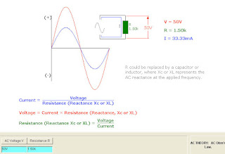
AC THEORY: AC Ohm's Law.
Ohm's Law can also be applied to AC circuits. However, alternating currents and voltages are continually changing. At the beginning of the cycle the voltage and current are zero, building to peak positive values at 90°, before declining back to zero, and then repeated in a negative direction.
It is therefore only possible to calculate instantaneous values of V or I throughout the cycle. Peak or RMS values are normally used.
The AC resistance of capacitors and inductors is called 'reactance' (measured in Ohms). As the frequency is increased, capacitive reactance decreases, whereas inductive reactance increases.
Once the reactance is calculated for C or L at the applied frequency, the value can be inserted in the formula as for resistance. Where there is a combination of resistance and reactance the calculation refers to 'impedance', symbol Z.
 AC THEORY: Combining Alternating Currents.
When two or more currents flow in a DC circuit they can be added or subtracted directly. For parallel AC circuits the currents will be at phase angles determined by the circuit capacitive and inductive elements.
One way the resultant can be found is graphically as shown, by measuring the amplitudes of the instantaneous values for A and B throughout the waveform and adding. The resultant phase angle will tend to be towards the current making the greatest contribution to the resultant.
Phase differences greater than 90° are not considered, but it should be understood that they do arise in practical circuits.
The use of phasors is another approach. Select 'phasor diagrams topic' for an explanation.
 AC THEORY: Voltage and Current for R.
For the parallel AC circuit the voltage is common across all current branches of R, C and L. However, the current for each branch will have a phase angle determined by the resistive, capacitive or inductive element of that component.
For the capacitor, the current will 'lead' the voltage and for the inductor current will 'lag' the voltage. Whereas resistor currents and voltages will always be in phase.
The instantaneous amplitudes of both voltage and current can be found at any point throughout the AC waveform for phase angles of 0 to 360°.

AC THEORY: Voltage and Current for C.
For the parallel AC circuit the voltage is common across all current branches of R, C and L. However, the current for each branch will have a phase angle determined by the resistive, capacitive or inductive element of that component.
For the capacitor, the current will 'lead' the voltage and for the inductor current will 'lag' the voltage. Whereas resistor currents and voltages will always be in phase.
The instantaneous amplitudes of both voltage and current can be found at any point throughout the AC waveform for phase angles of 0 to 360°.

AC THEORY: Voltage and Current for L.
For the parallel AC circuit the voltage is common across all current branches of R, C and L. However, the current for each branch will have a phase angle determined by the resistive, capacitive or inductive element of that component.
For the capacitor, the current will 'lead' the voltage and for the inductor current will 'lag' the voltage. Whereas resistor currents and voltages will always be in phase.
The instantaneous amplitudes of both voltage and current can be found at any point throughout the AC waveform for phase angles of 0 to 360°.